
Kategórie článkov
- Aplikácie (3)
- Linux (2)
- ATM (21)
- ATM Linux (4)
- Hardvér (6)
- ForeRunner LE155 (5)
- ENUM (2)
- Generátory prevádzky (4)
- Hardvér (1)
- IDS/IPS (2)
- Instant messaging (4)
- IP QoS (5)
- IP Telefónia (10)
- VoIP (4)
- IPTV (1)
- IPv6 (2)
- KNIHY (6)
- Linux – AkoNaTo (34)
- Monitoring, Manažment, Meranie (14)
- NetAcad (7)
- NGN/IMS (23)
- Kamailio IMS (16)
- OpenIMSCore (5)
- NGN/IMS (6)
- Kamailio IMS (2)
- OpenIMSCore (3)
- Packet captures (8)
- Portál (8)
- Practical – Cisco (29)
- Practical – Juniper (1)
- Prakticky – Cisco (24)
- Sieťová bezpečnosť (24)
- Sieťové simulácie a modelovanie (30)
- Dynamips/Dynagen (1)
- GNS3 (7)
- Opnet (10)
- UNetLab (1)
- VNX (1)
- SIP (126)
- Aplikačné servery (15)
- Mobicents (13)
- Asterisk (12)
- Bezpečnosť (5)
- FreeSWITCH (1)
- Iné SIP Servery (12)
- SER (2)
- Kamailio (10)
- Nástroje (8)
- NAT, FW (3)
- OpenSER (15)
- OpenSIPS (1)
- SIP referencie (4)
- SIP UA (25)
- SipXecs (5)
- Služby (6)
- CPL (4)
- Testovanie (3)
- Aplikačné servery (15)
- Tools (2)
- Virtualizácia (7)
- OpenStack (2)
- VirtualBox (3)
- Vmware (1)
- Vmware images (1)
- Vyučovanie (1)
- WebCMS (9)
- Drupal (3)
- Joomla! 1.5 (5)
- Komponenty (1)
- Plugin (1)
- Windows (10)
- Windows 10 (3)
- Windows 2016 server (2)
- Windows 7 (3)
- Windows (17)
- Windows 10 (3)
- Windows 2003 server (3)
- Windows 7 (3)
- Windows 2019 server (1)
- Wireless (6)
- Hardvér (1)
- Nástroje (4)
- Referencie (1)
- Záverečné práce (5)
- CCNP (8)
- CPL (3)
- OpenSIPS (2)
- Other SIP Servers (1)
- Security (1)
- Services (6)
- SIP Availability (2)
- SIP references (2)
- SIP UA (10)
- SipXecs (2)
- Testing (2)
- Tools (10)
- Tools (8)
- VB images (2)

V tomto krátkom článku sú popísané pravidlá, ako často aktualizovať systém arkime a jeho súčasti. Na servery Offline-arkime je operačný systém Ubuntu. Tento operačný systém má vo svojich životných cykloch definované doby trvania podpory. Nami využívaný systém má štandardne podporu…

Arkime používa Elasticsearch na indexovanie a prehľadávanie odchytenej prevádzky. Preto musíme najskôr nainštalovať Elasticsearch. Arkime 5.x je kompatibilný s Elasticsearchom verzie 7.10+, 8+ Pred inštaláciou aktualizujeme balíčky sudo apt update sudo apt upgrade Nainštalovanie Java Development Kit-u sudo apt install…

Áno, aj v ére GNS3/Eve-ng ešte používame Dynamis/dynagen ako super CLI riešenie pre beh overených monolitických IOS Na našom serveri / LXC kontajneri však pozorujeme “zamŕzanie” TCP relácii, ktoré sa prejavuje výpadkom telnet pripojenia na konzolu zariadenia na cca 10minut….

Autor: Peter Mako Pred samotnou inštaláciou PacketFence servera na existujúci systém Linux, je potrebné si pozrieť požiadavky na systém. PacketFence server podporuje tieto operačné systémy: Red Hat Enterprise Linux 8.x Server Debian 11.x (Bullseye) Minimálne požiadavky na inštaláciu a prevádzku…

Autor: Peter Mako Ako prvé si ukážeme konfiguráciu RADIUS servera. V tomto príklade sme použili Kali Linux pod označením Kali 2023.3 s dátumom vydania 23. augusta 2023 a s jadrom 6.3.0. Na to aby sme mohli začať so samotnou inštaláciou FreeRADIUS servera, musí…
Autor: Samuel Vrana, ASI 2022, update palo73 V tomto článku za zaoberáme popisom riešenia inštalácia Network policy servera (Radius NPS) na serverovom systéme Windows. Policy server bude slúžiť na autentifikáciou pužívateľov zo zariadení s Cisco IOS s tým, že po…
Autor: Juraj Hofer, vedúci: Segeč Inštalácia ManageIQ Pre inštaláciu ManageIQ podľa tohto návodu je potrebné hostiteľské prostredie na spustenie softvéru ManageIQ a podporovaný riadený systém na pripojenie. Existujú štyri jednoduché možnosti, ako spoznať ManageIQ, ktorý nevyžaduje prístup k virtualizačnej platforme: …

WireGuard je „lightweight“ virtuálna privátna sieť (VPN), ktorá podporuje pripojenia IPv4 a IPv6. Pôvodne bol vydaný pre jadro Linuxu ale teraz je multiplatformový (Windows, macOS, BSD, iOS, Android). V súčasnosti sa stále vyvíja a v porovnaní s OpenVPN je jeho konfigurácia podstatne jednoduchšia. Operačný systém…
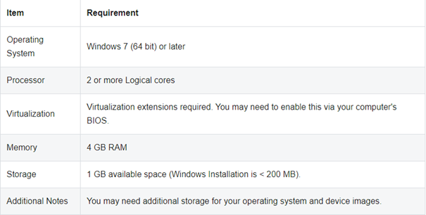
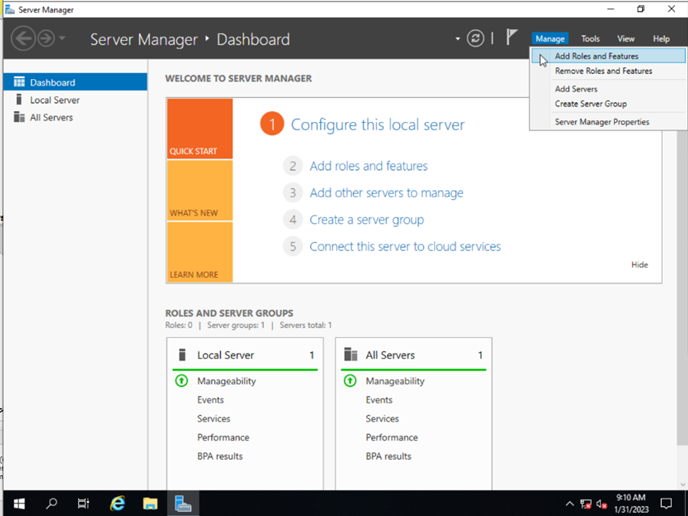
V tomto návode sa dozviete, ako nainštalovať GNS3 na operačnom systéme Windows. GNS3 podporuje tieto operačné systémy: Windows 7 SP1 (64 bit) Windows 8 (64 bit) Windows 10 (64 bit) Windows Server 2012 (64 bit) Windows Server 2016 (64…
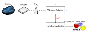
Autor: Andrej Šišila, Slavomíra Kureková – študenti odboru ASI (Aplikované sieťové inžinierstvo) – KIS FRI UNIZA – 2016/17 GNS3 podporuje dve verzie architektúry klient- server tieto verzie sa líšia v type servera a to lokálny a vzdialený server. V projekte…
Autor: Andrej Šišila, Slavomíra Kureková – študenti odboru ASI (Aplikované sieťové inžinierstvo) – KIS FRI UNIZA – 2016/17 GNS3 je grafický sieťový virtualizačný nástroj, ktorý umožňuje vytvárať komplexné sieťové topológie, ktoré obsahujú sieťové prvky rôznych značiek a tiež koncové zariadenia…
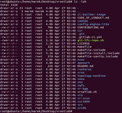
Pred samotnou inštaláciou je potrebné nainštalovať požadované balíčky ako Docker, git, Beautiful Soup a sshpass: #apt -y install python3-bs4 sshpass make #apt -y install git #apt install -y \ apt-transport-https ca-certificates \ curl gnupg-agent software-properties-common #curl -fsSL https://download.docker.com/linux/ubuntu/gpg | sudo apt-key…