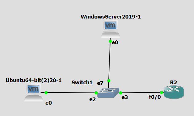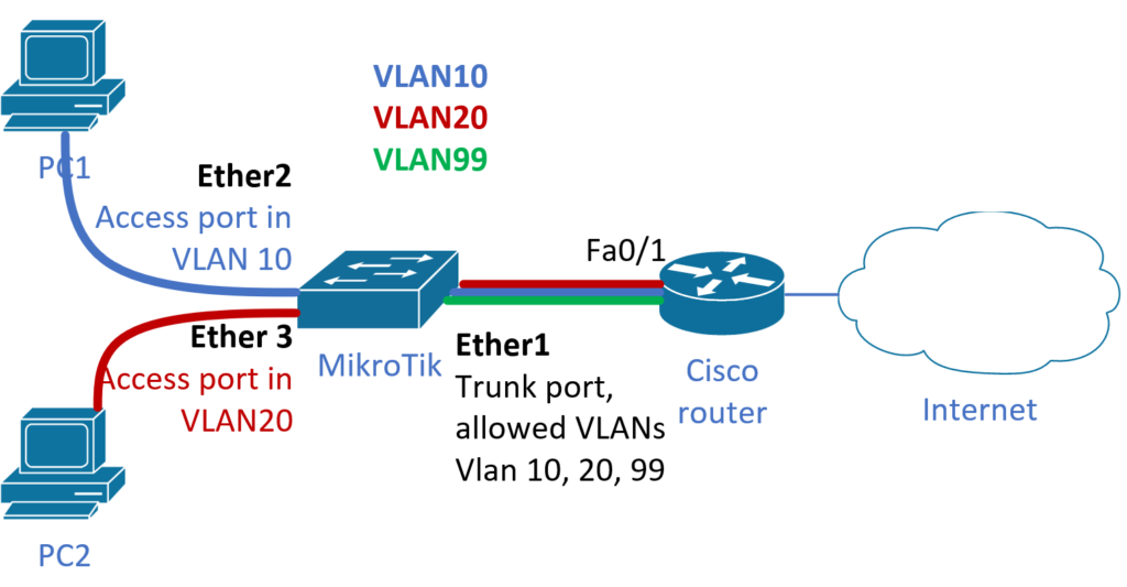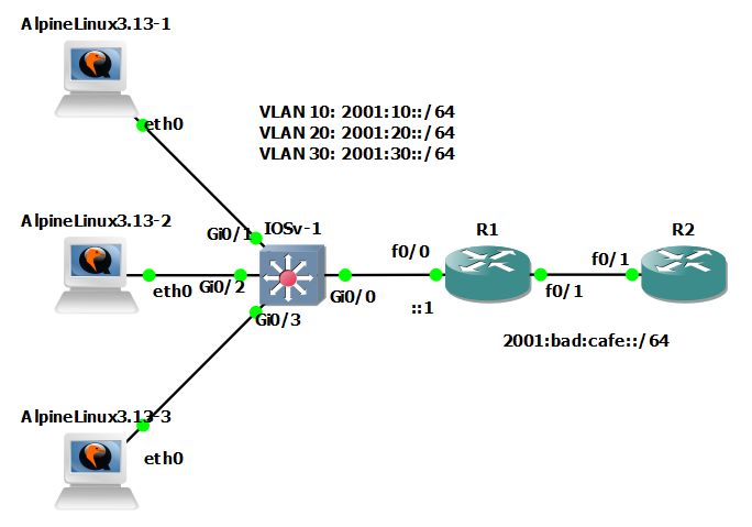
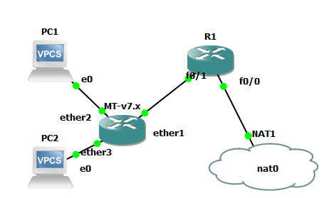
In this article, as the RouterOS CLI newbie, I will set up a simple LAN network consisting of two PCs, one Mikrotik box that acts as a simple L2 LAN switch, and one Cisco router that connects everything to the internet using NAT. All four devices are in the same broadcast domain and have IP addresses from the network address space : 10.1.1.0/24
Devices addresses:
- PC1: 10.1.1.101/24
- PC2: 10.1.1.102/24
- Mikrotik box: 10.1.1.2/24
- Cisco router as a defautl gw: 10.1.1.1/24
The R1 router config is quite simple:
hostname R1
interface FastEthernet0/0
 ip address dhcp
 ip nat outside
interface FastEthernet0/1
 ip address 10.1.1.1 255.255.255.0
 ip nat inside
ip access-list standard 1
  permit 10.1.1.0 0.0.0.255
ip nat inside source list 1 int fa 0/0 overload
A simple test of connectivity
R1(config)#do ping 1.1.1.1 so fa 0/1
Type escape sequence to abort.
Sending 5, 100-byte ICMP Echos to 1.1.1.1, timeout is 2 seconds:
Packet sent with a source address of 10.1.1.1
!!!!!
Success rate is 100 percent (5/5), round-trip min/avg/max = 8/16/40 ms
R1(config)#
However, I’m focusing on RouterOS. In GNS3 the Mikrotik boot empty, and there is no configuration.
Therefore, to enable LAN switching, we have to create the bridge. We will do it by typing
[admin@MikroTik] /interface/bridge
[admin@MikroTik] /interface/bridge> add name=main mtu=auto auto-mac=yes
Where
- name is the name
- auto-mac – choose MAC address from the first added port
all other parameters of the bridge stay in their default values (more at https://help.mikrotik.com/docs/display/ROS/Bridging+and+Switching).
Then, we have to assign physical ports to the bridge
[admin@MikroTik] /interface/bridge> port add bridge=main interface=ether1
[admin@MikroTik] /interface/bridge> port add bridge=main interface=ether2
[admin@MikroTik] /interface/bridge> port add bridge=main interface=ether3
The final bridge will look like this:
admin@MikroTik] /interface/bridge> port/print
Columns: INTERFACE, BRIDGE, HW, PVID, PRIORITY, PATH-COST, INTERNAL-PATH-COST, HORIZON
# INTERFACE  BRIDGE  HW   PVID  PRIORITY  PATH-COST  INTERNAL-PATH-COST  HORIZON
0 ether1     main    yes     1  0x80             10                  10  none
1 ether2     main    yes     1  0x80             10                  10  none
2 ether3     main    yes     1  0x80             10                  10  none
Adding physical ports forms the software switch/bridge, where all connected devices may communicate. Here PC2 will be able to ping PC1 and ad vice versa, and similarly, we are able to ping the default gateway or internet IP addresses
PC2> ping 10.1.1.101
84 bytes from 10.1.1.101 icmp_seq=1 ttl=64 time=0.579 ms
84 bytes from 10.1.1.101 icmp_seq=2 ttl=64 time=1.089 ms
84 bytes from 10.1.1.101 icmp_seq=3 ttl=64 time=1.104 ms
84 bytes from 10.1.1.101 icmp_seq=4 ttl=64 time=0.844 ms
84 bytes from 10.1.1.101 icmp_seq=5 ttl=64 time=0.957 ms
PC2> ping 10.1.1.1
84 bytes from 10.1.1.1 icmp_seq=1 ttl=255 time=60.355 ms
84 bytes from 10.1.1.1 icmp_seq=2 ttl=255 time=16.283 ms
84 bytes from 10.1.1.1 icmp_seq=3 ttl=255 time=5.571 ms
^C
PC2> ping 1.1.1.1
84 bytes from 1.1.1.1 icmp_seq=1 ttl=50 time=25.608 ms
84 bytes from 1.1.1.1 icmp_seq=2 ttl=50 time=16.361 ms
84 bytes from 1.1.1.1 icmp_seq=3 ttl=50 time=15.478 ms
^C
PC2>
Finally, we may assign an IP address to the bridge to access or test connectivity from the Mikrotik.
[admin@MikroTik] > ip address
[admin@MikroTik] /ip/address> add address=10.1.1.2/24 interface=main network=10.1.1.0
where ping works now
[admin@MikroTik] /ip/address> /ping 10.1.1.1
  SEQ HOST                                     SIZE TTL TIME       STATUS
    0 10.1.1.1                                   56 255 92ms971us
    1 10.1.1.1                                   56 255 14ms356us
    2 10.1.1.1                                   56 255 11ms668us
    3 10.1.1.1                                   56 255 4ms973us
    4 10.1.1.1                                   56 255 3ms15us
    sent=5 received=5 packet-loss=0% min-rtt=3ms15us avg-rtt=25ms396us
   max-rtt=92ms971us
As the bridge is doing what bridge must, it learns MAC addresses and bridge/switch frames, we may see its bridging table
[admin@MikroTik] > interface bridge host print where bridge=main
Flags: D - DYNAMIC; L - LOCAL
Columns: MAC-ADDRESS, VID, ON-INTERFACE, BRIDGE
#    MAC-ADDRESS        VID  ON-INTERFACE  BRIDGE
4 DL 0C:CC:C9:B0:00:00       main          main
5 D  00:50:79:66:68:00    1  ether2        main
6 D  00:50:79:66:68:01    1  ether3        main
7 DL 0C:CC:C9:B0:00:00    1  main          main
8 D  CA:01:37:1A:00:06    1  ether1        main